Exporting SVGs from Fusion
Fusion 360 Export to Origin Command
The Export to Origin command in Fusion 360 allows you to easily export geometry from Fusion 360 to an SVG file that can be used by your Shaper Origin tool.

Depending on what you want to cut and the geometry you have in Fusion 360, the command provides several options, which are explained below.
Advanced/Simple Modes
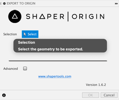
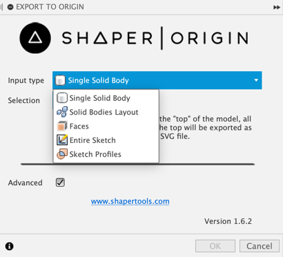
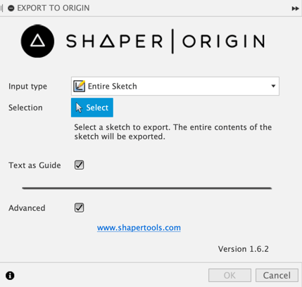
There is a check box on the command dialog that lets you choose if you're running in a simple or advanced mode. When in simple mode it's set to only allow selection of a single solid body. Changing to "Advanced" mode displays a drop-down to allow you to choose between "Single Solid Body", "Faces", "Entire Sketch", and "Sketch Profiles". The dialog in simple mode is shown below. See the documentation below for "Single Solid Body" for detailed information about how it works.
Below is the dialog when the Advanced mode is enabled which displays the drop-down to choose the input type. Each of the input type options is described in detail below.
Single Solid Body
When in Simple mode or Advanced mode and "Single Solid Body" input type selected, you are able to output the shape of an entire solid body as an appropriately annotated SVG to use with your Origin tool. When using a solid body, you select a single planar face. That face specifies both which body you want to output and also the "up" direction to use. You can think of it as the tool will be sitting on top of the selected face.
Below is an example part that contains several features on one side of the part and also some features on two of the sides.
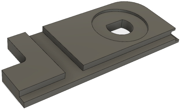
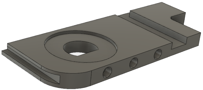
To create the file to cut the top of the part you can select any of the faces that are on the top of the part, which are all highlighted below.
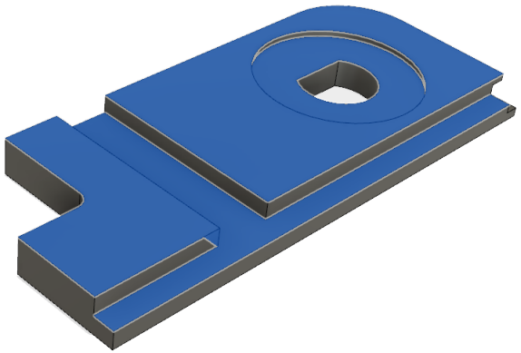
The resulting SVG file looks like what's shown below. You can see that the output only includes those features that you can see and cut from the top. The black shape indicates an area that's to be cut out on the outside and the gray areas indicate pockets. It's difficult to see in the image but the gray areas are slightly different shades of gray, indicating different depths. The precise depth is also included in the SVG file.
To cut the other sides that contain features, you can run the command again and like before choose a planar face that defines the "up" direction. To cut the side with the slot you can choose any of the faces highlighted below.
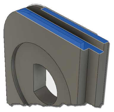
This results in creating the SVG shown below. The part orientation is now based on the orientation of the selected face and only those features that can be cut from that direction are shown in the SVG.
To cut the side with the holes, either one of the faces highlighted below can be selected.
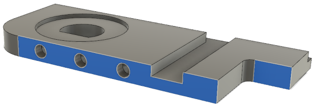
And this results in the SVG shown below.
The "Single Solid Body" option is typically the best option when cutting an entire part because it considers the entire shape and all of the features of the selected body.
Faces
When in Advanced mode you can select the "Faces" input type. This allows you to select one or more planar faces for output. With this option, only the shape of the selected faces is output and they're output as "cut outside". If more than one faces is selected it must be from the same body and parallel to the first face. The faces highlighted below are valid selections since they are both part of the same body and are parallel.
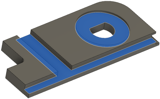
And this results in the SVG shown below.
Entire Sketch
Sometimes you may not need an entire solid body and just a simple 2D sketch is good enough. The "Entire Sketch" and "Sketch Profiles" input types allow you to use just sketch geometry. The "Entire Sketch" option allows you to select a sketch and all of the geometry of the entire sketch is written out to the SVG. It's written out as "cut along" geometry since a sketch can contain open curves. This is useful for many designs.
Below is an example sketch to demonstrate the capabilities of the export.
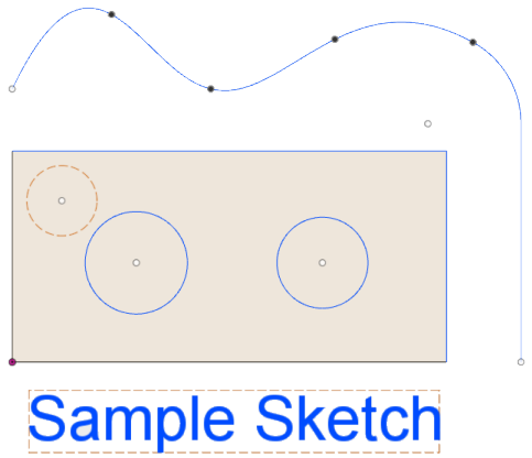
And this results in the SVG shown below. Notice that the result does not include any of the construction geometry, (the curves drawn in the dashed line style), and it also does not include the text.
If you want to include the shape of the text in the output, in Fusion 360 while editing the sketch, you can right-click on the text and choose the "Explode Text" command from the context menu. This converts the text to regular geometry and now it will export, as shown below.
Sketch Profiles
The "Sketch Profiles" input type also allows you to export sketch geometry but allows you to select a subset of the sketch by selecting profiles within a sketch. A profile is a closed area within a sketch. A profile is also what you select for most features, like extrude or revolve. Because profiles always define a closed area they are written to the SVG as "cut outside" areas.
Below is an example sketch to demonstrate the capabilities of the export.
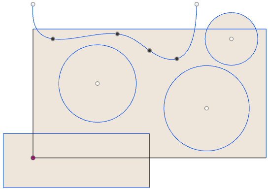
The picture below illustrates all of the closed areas that Fusion 360 has identified within the sketch and each of these is available to select as a profile.
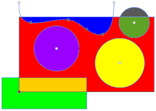
You can select one or more profiles from the same sketch. The picture below shows the SVG file that's created when selecting the red profile shown above.